I recently got my hands on a Samsung 16T202DA1 Vacuum Fluorescent Display module that I salvaged out of an old HTPC case. As luck would have it, these are fully compatible with the Hitachi HD44780 protocol, making it easy to use with the Arduino LiquidCrystal library.
The project I had in mind for this – a standalone, ESP8266-powered data display, didn’t have enough pins to support both the display and the other components I wanted to hang off it. To work around this, I picked up a couple of I2C LCD backpack adaptors, which can be found for well under $1 each at your favourite Chinese electronics marketplace.
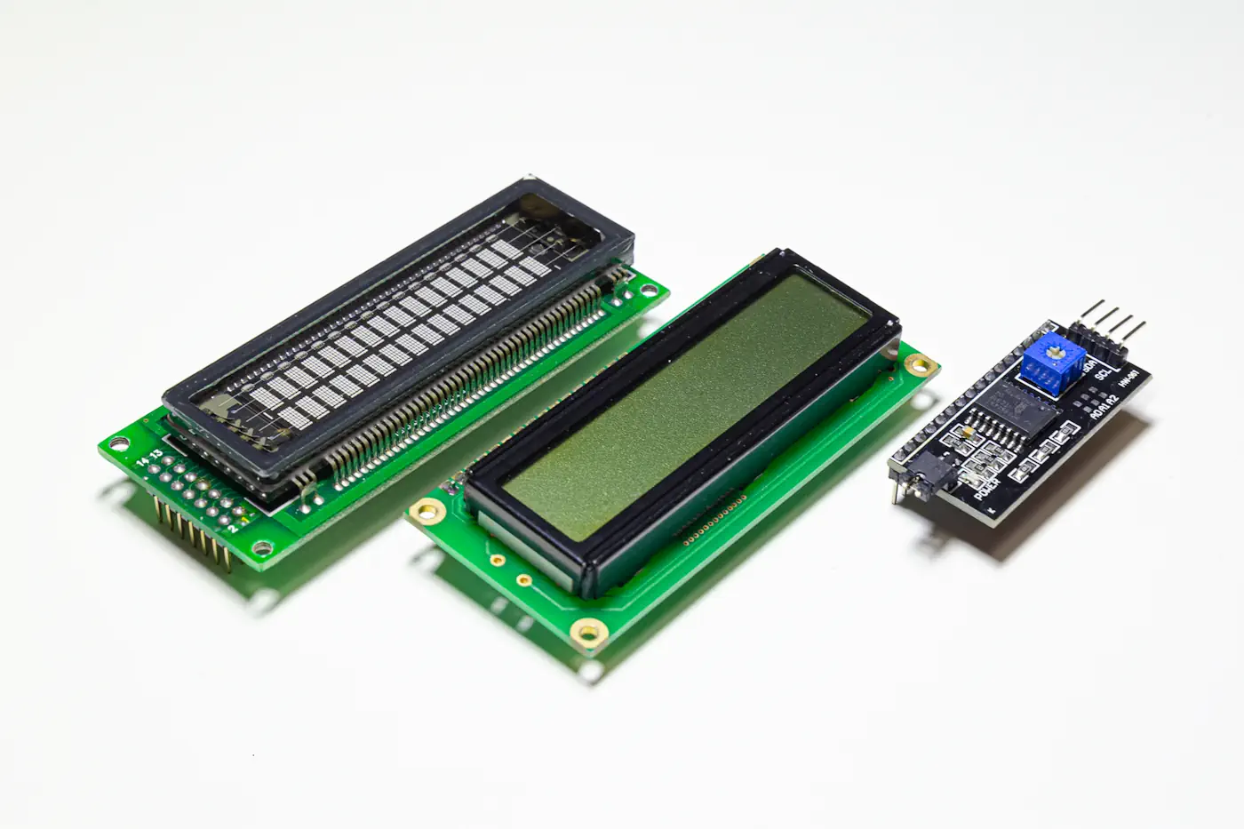
These modules employ the PCF8574 chip, which is a “remote 8-bit I/O expander for I2C bus”, which is basically a fancy name for a serial to parallel convertor; that is – it takes one byte of serial data in (via the I2C, or two-wire bus), and expands that out into 8 individual digital pins as bits.
Modules, How Do They Work?
I wasn’t able to find much else in the way of documentation on how the chip was implemented on the module, so after using a
multimeter to figure out which of the PCF8574’s pins actually connected to the LCD, I built a small rig on a breadboard to analyse what pins are affected by what input on the I2C bus:
From this, I was able to determine the following byte-to-pin mappings:
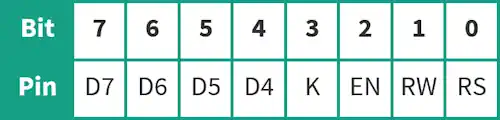
A nifty little feature of the backpack is the ability to control the backlight of the LCD. This isn’t part of the HD44780 protocol, but an independent input that’s normally driven from a separate GPIO. The I2C backpack implements this by switching the LCD’s cathode (pin 16) between open and ground through an NPN transistor (note this is opposite behaviour to all other pins, which are set high or low).
So all up, we’ve got 8 pins of output from only 2 GPIOs… but how do we use this with the ubiquitous LiquidCrystal library?
Stick to the Protocol
First of all – just a very small bit of background as to how the HD44780 works. These have a total of 16 pins – two for power, two for backlighting, one for contrast, 8 for data and 3 for control. The 8 data pins accept 8 individual data bits in parallel, however we also have the option of operating in 4-bit mode, meaning we only need four of the data pins (but everything takes twice as long to send, as we have to send each byte in two halves).
To differentiate between a display data and command data, we use the RS, or “register select” pin. Commands include functions such as display initialisation, showing or hiding the cursor, or scrolling the display.
To send data, we hold each of the corresponding data pins high or low, representing the bits that we want to send. Once we’ve got all the data pins set to their appropriate values, we send a quick pulse to the “enable” pin, which signals to the device to read the pins as they’re currently set. Each byte of data sent in this mode will be displayed on the LCD according to the current parameters.
If you want a bit more of a deep-dive on how this all works, the 8-Bit Guy does a great video on the subject which you can find here.
Adapt, Improvise, Overcome
I’m aware that several libraries exist already – however I found most implementations to be a little slow; the VFD doesn’t suffer from the same poor response rate as the LCD, meaning animated effects look a lot nicer – but this calls for a faster-performing library. In addition, I couldn’t find any libraries that implemented the VFD’s brightness control functions, and I wanted something that was as close to a drop-in replacement for the existing LiquidCrystal library as possible.
First off, we can tidy up the existing code a little by eliminating 8-bit mode from the library. We’ve only got 8 bits of output from the PCF8574 module – of this, we need to be able to not only send data, but also toggle the register select pin and the enable pin as well as control the backlight, so we’re forced to use the HD44780’s 4-bit mode for data entry.
Most of the magic happens in in the write4bits() function. In the original library, this simply splits the input into four bits, and writes this to their corresponding pins using digitalWrite(), then sends a quick pulse to the “enable” or “E” pin through the pulseEnable() function:
void LiquidCrystal::write4bits(uint8_t value) {
  for (int i = 0; i < 4; i++) {
    digitalWrite(_data_pins[i], (value >> i) & 0x01);
  }

  pulseEnable();
}
This function is where we need to do 99% of the work.
Instead of writing to four GPIOs, we need to redirect these writes to I2C. We do this by taking the 4 bytes of data, shifting these left four places (you’ll remember earlier that that bits 4 – 7 are our data bits), and appending our other pin settings (RS, E
and backlight) for bits 0, 2 and 3. As we never read data from the LCD, “RW” is always held low.
Because the LCD backlight isn’t part of the HD44780’s control functions, we also send the backlight status with every command; if we don’t, it will switch off every time we send fresh data!
In order to speed things up, we can take a shortcut around the pulseEnable() function. It turns out, we don’t need to actually “pulse” the “E” pin; it’s only once the “E” pin is returned to low that the data is read by the LCD. Instead of setting the data pins and then sending a quick pulse to “E”, we can set the “E” pin at the same time as our data pins, and then set “E” to low, saving us a a third of our I2C bandwidth:
void LiquidCrystal::write4bits(uint8_t value, uint8_t mode) {
  uint8_t bits = ((value & 0x0F) << 4);    // mask 4 data bits and shift left
  writeToI2C(bits | _backlight | (mode & RS_PIN));
}

void LiquidCrystal::writeToI2C(uint8_t bits) {
  Wire.beginTransmission(_addr);
  Wire.write(bits | EN_PIN);               // write data bits + enable bit
  delayMicroseconds(1);                    // enable pulse must be >450ns
  Wire.write(bits);
  delayMicroseconds(50);                   // commands need > 37us to settle
  Wire.endTransmission();
}
A slight modification is required to enable the write4bits() to be able to set the “RS” pin; in the stock Arduino library, this is set by a previous function, where they had the luxury of being able to set pins independently. This is provided by including the uint8_t mode parameter.
All that’s left is to incorporate the LCD backlight control, which is handled by the backlight() and noBacklight() commands:
void LiquidCrystal::noBacklight() {
  _backlight = LCD_BACKLIGHTOFF;
}

void LiquidCrystal::backlight() {
  _backlight = LCD_BACKLIGHTON;
}
And finally, incorporate VFD backlight control (after finding the relevant command from the datasheet) with the setBrightness() command:
void LiquidCrystal::setBrightness(uint8_t value) {
  _displayfunction &= ~0x03;
  _displayfunction |= (value & 0x03);
  command(LCD_FUNCTIONSET | _displayfunction);
}
Just a small modification, but this did take me a good week or more to reverse-engineer the module, build the test rig and adapt the library (though I’m sure anyone competent could knock it over in half a day).
Here’s a short video of it in action with the VFD:
I wrote a quick bit of test code to see just how quickly the library performed versus other comparable implementations, and found it to be 68% faster (largely due to the pulseEnable() optimisation, as best as I can tell). Take that, other implementations!
Visit Your Local Library
You can download the library from my GitHub, which includes full detail on how to use this or adapt existing implementations.
Thanks for this. I just picked up a 20T202DA1J that I reckon will work the same way.