The 433 MHz ISM band is a RF band often used for low-power, short range wireless communication in devices such as garage door openers, wireless weather stations, and remote-controlled power sockets, like this device:
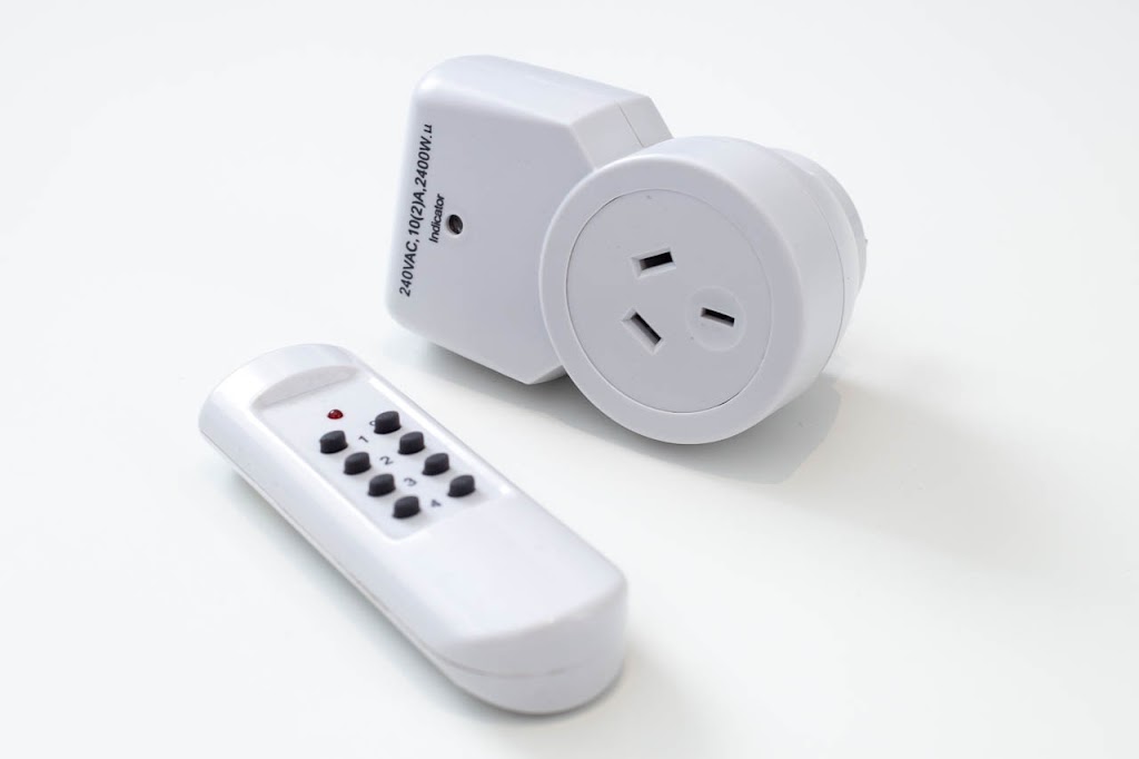
The device is an Olsent RCS-5A which I picked up from a local clearance shop for the bargain price of $9, and three additional slave units at $6 each.
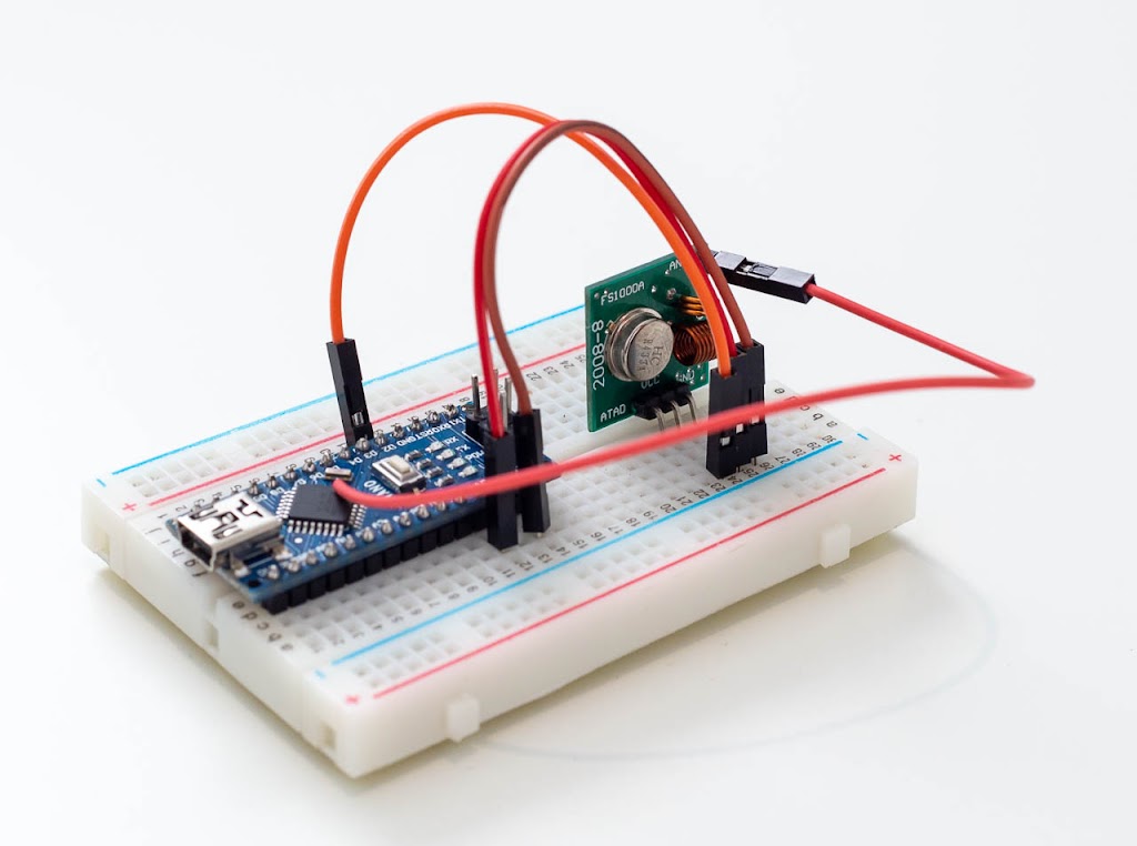
The end goal of this project is to reverse-engineer the protocol this device uses to communicate, and interface this with a dirt-cheap 433 MHz transmitter module attached to an Arduino Nano (and fully portable to ESP8266) to enable custom control of attached devices.
There’s a couple of approaches that can be taken to decoding the signal. I’ve previously used an Arduino Mega as a logic analyser with an IR receiver module for decoding infra-red; the same could be done here with the 433 MHz receiver module. Instead, I’ve opted to use an RTL-SDR together with Universal Radio Hacker, which is designed to extract and decode this exact kind of thing.
To get started, you’ll need to gather the following:
- Software-Defined Radio dongle
- Arduino Uno, Nano, Micro or similar (or even an ESP8266)
- 433 MHz RX / TX modules (only the TX is needed)
- A copy of Universal Radio Hacker (https://github.com/jopohl/urh)
Assuming you’ve already got the SDR, you’re up for less than $5 in parts!
Capturing and decoding the signal
If you’re playing along at home, fire up URH and click on “Record Signal”, select your model of SDR, enter the frequency (usually written on the device) and click the start button. Trigger your device (try a few different durations to be safe), click stop and save your captured signal, and if you’re end up with something like this:
This modulation is a form of Amplitude Shift Keying, or ASK, known as On-Off Keying (OOK), the same type as the 433 MHz module implements. Zooming in a bit, you should be able to understand how it works:
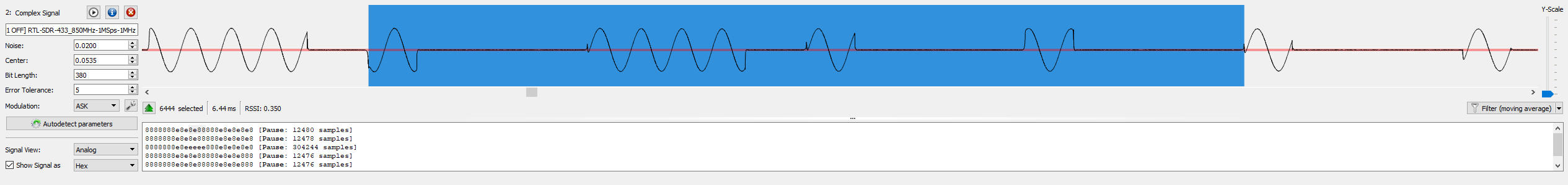
Pulses lengths are precisely timed to within a few microseconds. If the signal is present for a pre-defined duration (in the above sample, around 350 microseconds) a 1 is recorded, and a 0 if absent. In the above example, the highlighted section shows a sequence of 16 bits.
URH did a pretty good job of auto detecting the parameters, and with some mild fine-tuning of the bit length, I was able to obtain consistent results, such as the following sequence:
1000100010001000100010001000111010001110100010001000111010001000100011101000111010001110100011101
That’s exactly 100 bits… but there’s a pattern here. You’ll notice that each 4-bit sequence is either 1000 or 1110, which means that the 25th bit is actually the start of a 1000 sequence – but because the transmitter’s last three pulses were “off” , we don’t know they’re there.
Assuming 1000 is a 1 and 1110 is a 0, we can compress this down to the following sequence:
1111111010111011101010101
Which represented as hexadecimal, becomes:
1FD7755
We could take this a step further and convert to ASCII, but at that point it becomes unreadable, so we’ll stick with hex.
Repeating the above for each of the 8 buttons, we get the following codes:
| Button | On Sequence | Off Sequence |
|---|---|---|
| 1 | 1FD7755 | 1FD7757 |
| 2 | 1FD5F55 | 1FD5F57 |
| 3 | 1FDD755 | 1FDD757 |
| 4 | 1FF5755 | 1FF5757 |
Hex is a great way to display data that’s aligned on 4 or 8-bit boundaries – unfortunately, this data doesn’t appear to be. My best guess is that at the bit level, the data is split into an initial 7 bits (all high), an 8-bit device address, an 8-bit constant and a 2-bit command, like so:
1111111/11010101/11010101/01 1111111/01010111/11010101/11
To make the data a bit easier to work when using C/C++, we can break this up a bit differently.
By discarding the first bit and automatically sending it at the start of every sequence, we can split the remaining 24 bits into 16-bit address and 8-bit command. For any given button, we simply need to send a initial “1” bit (which you’ll remember was one high pulse and three low pulses) , followed by the device address (e.g., FDD7) and finally the command (55 for on or 57 for off).
Building the circuit
This is about as easy as an Arduino circuit gets:
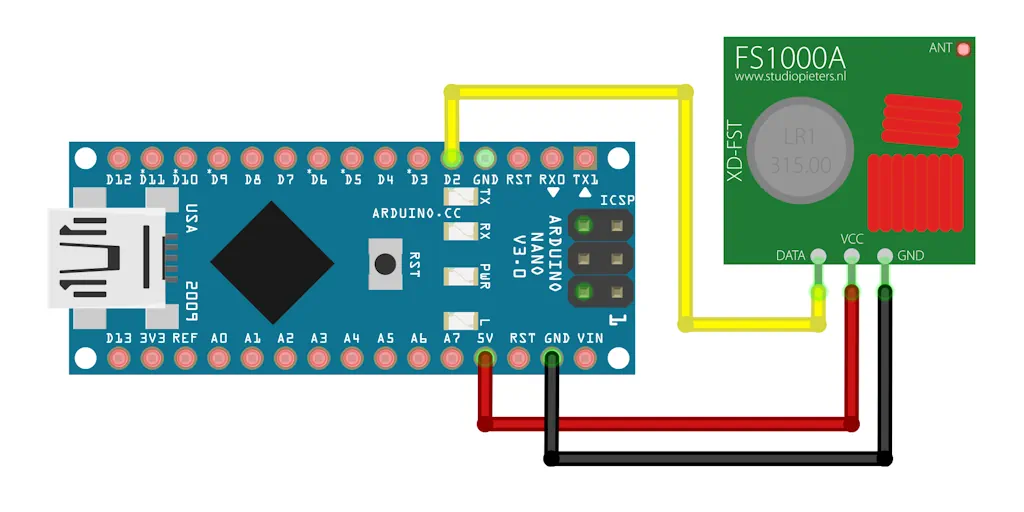
To drive the 433 MHz module, you simply need to use the digitalWrite() function; as long as the pin is held high, a constant signal will be sent from the device. If we modulate the signal by timing our digitalWrite() calls accordingly, we’ve got ourselves a pretty good approximation of the original OOK-modulated signal sent by the transmitter unit.
For the antenna, I’m using a 1/4-wave monopole, which is a 172mm wire attached to the antenna pin. Ideally, a 1/2 wave would perform much better, but at 344mm is somewhat impractical.
Writing the code
I could use one of the many libraries that are available for the 433 MHz units, but there’s no fun to be had that way!
Rolling-your-own code for these kind of implementations really makes you think about how they work at a logical level, and often saves precious flash space by only implementing the functions your code uses.
Implementing this in code can be broken down into two main tasks:
- Extracting the bits of the ‘compressed’ version of the sequence
- Sending the bits as their relevant sequence of 4-bit pulses
Here’s how I’ve gone about it:
#include <Arduino.h>

#define HIGH_PULSE 0x8  // 4-bit pulse sequence representing a logical 1
#define LOW_PULSE 0xE   // 4-bit pulse sequence representing a logical 0
#define BIT_LEN 360     // length of individual bit pulses

#define SEQ_LEN 24      // total number of bits in sequence
#define SEQ_RPT 4       // number of times to repeat full sequence (requires a minimum of 3 to register)
#define SEQ_PAUSE 11500 // time in microseconds to pause between repeated sequences

#define CMD_LEN 8       // total number of bits in command
#define CMD_ON 0x55     // on command sequence
#define CMD_OFF 0x57    // sequence for off command

#define DEV_1 0xFD77   // device 1 address sequence
#define DEV_2 0xFD5F   // device 2 address sequence
#define DEV_3 0xFDD7   // device 3 address sequence
#define DEV_4 0xFF57   // device 4 address sequence

#define TX_PIN 2        // physical pin to which 433MHz module is connected

/* send 4-bit pulse sequence representing logical 1 or 0 */
void send_pulse(bool state) {
  uint8_t pulse = state ? HIGH_PULSE : LOW_PULSE;  // determine pulse sequence based on state

  for (uint8_t j = 4; j > 0; j--) {
    bool bit = pulse >> (j - 1) & 1;               // extract individual bits from pulse from MSB to LSB
    digitalWrite(TX_PIN, bit);                     // set pin state based on pulse bit
    delayMicroseconds(BIT_LEN);                    // hold pin state for the bit length time
    digitalWrite(TX_PIN, LOW);                     // pull pin low once bit sent
  }
}

/* send command to specified device address */
void send_command(uint8_t chan, bool state) {
  uint16_t addrs[] = {DEV_1, DEV_2, DEV_3, DEV_4}; // load device addresses into array
  uint8_t command = state ? CMD_ON : CMD_OFF;      // determine command sequence based on state
  uint32_t addr = addrs[chan - 1];                 // determine address of device by index
  uint32_t seq = addr << CMD_LEN | command;        // concatenate address and command sequences

  for (uint8_t i = 0; i < SEQ_RPT; i++) {          // repeat command to ensure it's registered by receiver
    send_pulse(1);                                 // send initial bit pulse sequence

    for (uint8_t j = SEQ_LEN; j > 0; j--) {
      bool bit = seq >> (j - 1) & 1;               // extract individual bits from sequence from MSB to LSB
      send_pulse(bit);                             // send pulse sequence of extracted bit
    }

    delayMicroseconds(SEQ_PAUSE);                  // delay between repeated sequences
  }
}

void setup() {
  pinMode(TX_PIN, OUTPUT);
}

void loop() {
  send_command(1, 1);                              // turn device 1 on
  delay(1000);                                     // wait one second
  send_command(1, 0);                              // turn device 1 off
  delay(1000);                                     // wait one second
}
I’ve commented the code pretty heavily – most of it should be pretty self explanatory. For the sake of demonstration, this just flicks receiver #1 on and off with a delay in between. By changing the first parameter of the send_command() function for another address, any of the four devices can be controlled – no libraries needed!
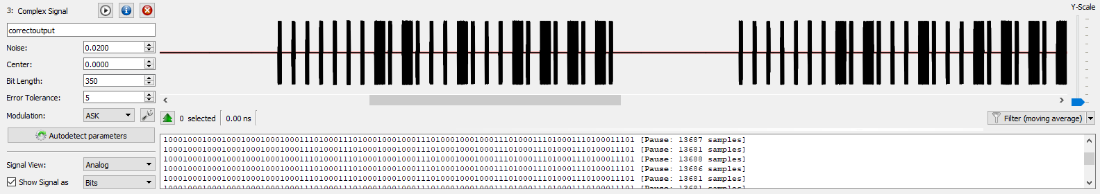
Testing it all
For whatever reason, the device won’t respond to a single pulse – I fired up URH again and sure enough, if I press the button on the original remote quickly enough to trigger only a single pulse, the device doesn’t respond. Further testing showed that at least four pulses were needed for the device to trigger consistently. This is the purpose of the define SEQ_RPT 4 macro.
So after a quick change to the code, everything works as expected; I can control any of the four devices from almost anywhere in my house.
Here’s the output from my device, captured using Universal Radio Hacker:
So, what now?
I’ve got a few ideas in mind for this; this is most ideal for switching circuits that are mains powered for home automation purposes, such as lights or some appliances. This isn’t necessary for most devices that use step down or switching power supplies – we could use a simple low-voltage relay to interrupt the low-voltage side of the supply for these.
It’s worth noting that it’s only a small jump from here to interface with Blynk to enable you to even build your own mobile apps – that’s one for another post in itself!
hey chris nice work…..i'm working on something similar can u help me out on this following project???
https://batlara.blogspot.com/2022/03/my-epic-failure-to-clone-car-key-fob.html
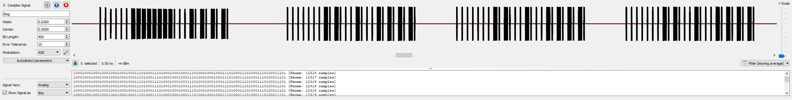
Hey mate! I've had a look over at your blog and I have a hunch as to what's happening. Those big black boxes you're seeing will contain a lot more data than you might realise!
In URH, use the mouse wheel to zoom right in and you'll see what I mean – what looks like a big old chunk will probably actually contain FSK data (frequency shift keying) – that is, the signal jumps between two different frequencies that represent your 1's and 0's.
The bad news is that if this is the case, the module you've used won't be much help in replicating this data; you might be better off looking into a device like a HackRF One.
Let me know how you go!