
Receiving infrared on the Raspberry Pi with Python
In this article, I’ll show you how to connect an infrared receiver to your Raspberry Pi and use the evdev interface to read and interpret the signals sent by most common household remote controls using Python. Infrared provides … Read More
Receiving infrared on the Raspberry Pi with Python
In this article, I’ll show you how to connect an infrared receiver to your Raspberry Pi and use the evdev interface to read and interpret the signals sent by most common household remote controls using Python. Infrared provides … Read More
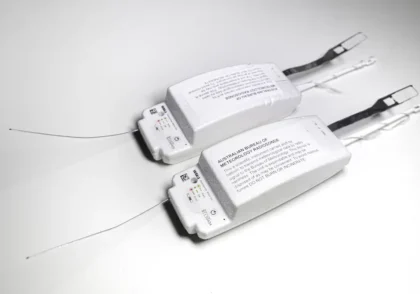
Building a simple ground station for radiosonde tracking
Only a few weeks ago, I was introduced to the world of radiosondes through an amazingly informative video from Andreas Spiess. By lunchtime the next day, I had one in my hands. These devices pack so many things … Read More
Building a simple ground station for radiosonde tracking
Only a few weeks ago, I was introduced to the world of radiosondes through an amazingly informative video from Andreas Spiess. By lunchtime the next day, I had one in my hands. These devices pack so many things … Read More
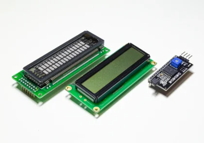
Adapting the Arduino LiquidCrystal library for I2C (and VFD)
I recently got my hands on a Samsung 16T202DA1 Vacuum Fluorescent Display module that I salvaged out of an old HTPC case. As luck would have it, these are fully compatible with the Hitachi HD44780 protocol, making it easy to use with … Read More
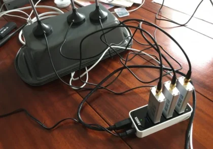
How to select RTL-SDR device indexes as a command line parameter
If you have multiple RTL-SDRs in attached to system for monitoring various services, you’ll know that in most cases, you need to specify a device index to make sure you’ve got the correct device selected. In my case, … Read More
How to select RTL-SDR device indexes as a command line parameter
If you have multiple RTL-SDRs in attached to system for monitoring various services, you’ll know that in most cases, you need to specify a device index to make sure you’ve got the correct device selected. In my case, … Read More

Reverse-engineering a remote-control power socket for Arduino integration
The 433 MHz ISM band is a RF band often used for low-power, short range wireless communication in devices such as garage door openers, wireless weather stations, and remote-controlled power sockets, like this device: The device is an … Read More

Pushing ADC limits with the perfect multi-button input resistor ladder
A resistor ladder is a brilliant but super simple way to attach multiple buttons to a single analog to digital converter (ADC) pin on an Arduino or other microcontroller. By expanding on the concept of the voltage divider, … Read More

Postcards from space: How to receive SSTV from the ISS
A few years ago, I learned of slow-scan TV transmissions from the International Space Station. SSTV is essentially a form of narrowband television – a single frame, taking anywhere from a few seconds to a few minutes to … Read More
Postcards from space: How to receive SSTV from the ISS
A few years ago, I learned of slow-scan TV transmissions from the International Space Station. SSTV is essentially a form of narrowband television – a single frame, taking anywhere from a few seconds to a few minutes to … Read More